Summary
- Apparent soil electrical conductivity (EC) mapping is a simple, inexpensive tool farmers can use to quickly and accurately characterize soil differences within farm fields.
- Mapping of other soil properties such as pH, organic matter and topography also holds great potential for delineating spatial variation in fields.
- A multi-sensor system effectively mapped a set of IA and MO fields, delineating variability not detected by USDA soil surveys.
Introduction
In order to develop variable-rate prescriptions for crop inputs like seed and fertilizer, it is first necessary to delineate fields into regions of distinct yield potential (Butzen, et al., 2012), also known as management zones (MZ). These are field areas possessing related landscape and soil property features, which lead to similar crop yield potential. Use of yield map (Gunzenhauser and Shanahan, 2011) and soil survey information (Gunzenhauser and Shanahan, 2012) are two approaches suggested as a means for defining MZ. However, both methods have their limitations. In the former case, yield data are not always readily available to growers; in the latter case soil properties are often not well defined near survey boundaries. Adamchuk et al., (2004) have pro-posed that use of on-the-go soil sensors configured with GPS produces the dense mapping coverage needed to better define soil boundaries and improve the delineation of MZ.
This Crop Insights explores the various soil sensor technologies and how each can be used to gain a higher level of information about target fields and improve the definition of MZ for variable application of crop inputs.
Soil Electrical Conductivity
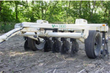
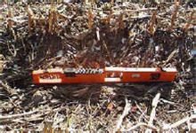
On-the-go soil sensor measurements of apparent electrical conductivity (EC) have been widely researched and show considerable promise for characterizing field variation in soil properties. Soil EC is a measure of the soil's ability to transmit or conduct an electrical current, and the units are reported in milliSiemens per meter. Soil EC measurements are correlated with soil properties that affect crop productivity, including soil texture, cation exchange capacity, drainage conditions, salinity and subsoil characteristics (Kitchen et al., 2003; Grisso et al., 2009). There are 2 methods currently available for mapping soil EC in the field (Figure 1). The first approach, called the "contact" method, uses coulters placed in direct contact with the soil to measure soil EC; the second, referred to as the "non-contact" method, uses electromagnetic (EM) induction. The measurement of soil EC by either contact or non-contact methods is said to have comparable results (Sudduth et al., 1998.
Veris® Technologies of Salina, KS introduced the first commercialized on-the-go soil EC mapping system (Figure 1). It measures EC at 2 depths (0 to 12", 0 to 36") as the device is pulled across a field. Soil sensor devices with mapping capability such as the Veris systems are being used by growers, seed sales reps, consultants, and researchers to develop MZ, guide soil sampling, and provide additional quantitative data for field analysis.
|
|

|
|
|
Figure 1. Upper left: Veris 3100 direct contact system with coulter-mounted electrodes requiring soil contact to measure soil EC. Upper right: Non-contact Geonics EM-38 sensor using electromagnetic induction to measure soil EC. Above: EC sensor coverage map of field acquired by Veris system. (Veris images courtesy of Veris Technologies; Geonics image courtesy of USDA-ARS). |
|
Soil pH
Another important soil property which has significant impact on crop productivity is pH. Soil pH is a measurement of the concentration of hydrogen ions present in the soil solution, with values ranging from 4 to 7 in most soils. A value close to 7, or neutral, is often desired for row crops. Soil pH affects nutrient availability (phosphorous and micronutrients like iron and zinc), herbicide activity, legume nodulation, all of which are important factors in determining crop productivity levels.
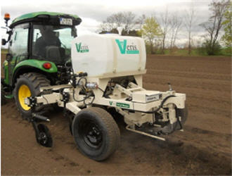
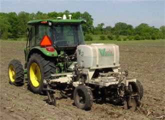
Veris is presently the only company marketing a soil pH mapping system on a Mobile Sensor Platform (Figure 2, top), introducing it in 2003. The sensor operates by lowering a sampling shoe into the soil to collect a sample, raising the sample against a set of electrodes to measure pH, and repeating the process. This allows approximately 10 pH samples to be taken per acre at typical travel speeds. Studies have shown that within 2.5-acre grids, there is a wide range of pH values, often ranging from soils that call for lime to soils that are already extremely high in pH (Brouder et al., 2005).
|
|
|
|
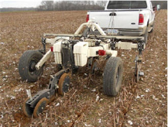
Figure 2. Top: Veris soil pH Sensor. Middle: soil organic matter (OM) sensor. Bottom: MSP sensor (EC, OM, and pH). (Courtesy Veris Technologies). |
How is On-the-go Soil pH Measurement Used?
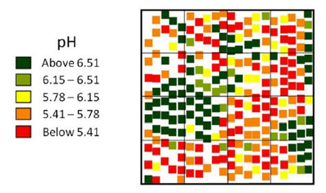
Having the ability to measure and obtain results from approximately 10 sample locations per acre provides the grower or consultant with a higher resolution set of data to measure in-field pH variations (Figure 3). Common grid soil sampling practices may provide a pH value for every 2.5 to 4 acres. Thus, the Veris Soil pH Manager provides a sampling resolution 25 to 40 times greater than that provided by grid soil sampling. In addition, the pH Manager can be paired with a soil EC array to allow the capture of soil pH, soil EC and soil color (discussed later) at the same time.
|
| Figure 3. Illustration of Veris Soil pH Manager samples within a set of typical 2.5-acre sample grids (courtesy Veris Technologies). |
Having a higher resolution of mapped soil pH provides for more accurate variable-rate application of lime and other calcium sources. This increases the odds that the right product and amount are placed properly, potentially enhancing product usability and crop yield.
Soil Organic Matter
Organic matter is yet another soil property having major effects on crop productivity levels. It contributes to a variety of biological, chemical and physical properties of soil and is essential for good soil health. It is a key component of structure and porosity, affecting moisture-holding capacity, the biological diversity and activity of soil organisms, and plant nutrient availability (particularly nitrogen).
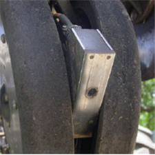
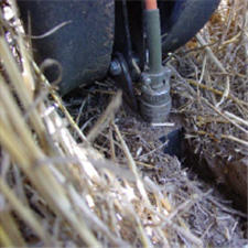
In 2011, Veris introduced the OpticMapper, which is able to log soil organic matter (OM) values on-the-go (Figure 2, middle). The device uses a dual-wavelength optical sensor mounted within a specifically configured planter row unit. This allows crop residue to be cleared away and the sapphire window at the bottom of the sensor shoe to be pressed directly against the bare, moist soil (Figure 4). A sensor reading is taken once per second. Conventional soil samples are taken from the field after the OpticMapper has been run, with the soil sample locations guided by the measurements from the OpticMapper. These soil samples are then used to calibrate the OpticMapper sensor values to lab-measured organic matter and cation exchange capacity (CEC) values. Veris-developed software uses the 2 sets of measurements and calibrates the on-the-go values to provide in-field OM and CEC estimates.
|
|
| Figure 4. OpticMapper shoe with sapphire window (left) and placed in soil (right) (courtesy Veris Technologies). | |
How is the OpticMapper used?
Soil organic matter maps can be used to develop management zones for variable-rate nitrogen and seeding rates. A general thought is that areas of higher organic matter have the ability to support higher seeding rates. Inversely, higher organic matter levels store greater amounts of nitrogen, thereby potentially reducing the amount of additional nitrogen to be applied. The application of nitrate inhibitors may be varied by the soil organic matter as well.
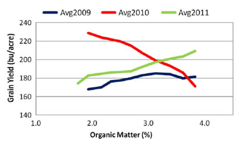
A Veris MSP with the OpticMapper and pH Manager was utilized in the spring of 2012 to measure soil EC, pH, organic matter, and CEC on a field located in central IA. This field had been enrolled in Pioneer FIT® Services Harvest Mapping for 2009, 2010, and 2011. Corn had been grown on all 3 years. Yield data were spatially combined with the measurements from the Veris OpticMapper. The data were summarized by incremental organic matter ranges. The results for each year's crop are shown in Figure 5.
|
| Figure 5. Graph of organic matter vs. yield for years 2009, 2010, and 2011 on a central IA continuous corn field. |
In 2009 a generally positive response was observed between organic matter and yield, though the response plateaued at OM values greater than 3%. A similar response was seen in 2011. However, there was a dramatic negative relationship between OM and yield in 2010 - the higher the OM, the lower the yield.
The difference in yield responses to changes in soil organic matter among years was likely due to different precipitation patterns. For example, rainfall for the growing season in 2009 and 2011 was closer to average for the area, whereas in 2010 it was greater than average. The areas within the field with higher OM may have held more water, inhibiting plant growth and causing yield loss, while areas with lower organic matter held enough moisture for optimum yields. Collectively, these results indicate that the effect of soil OM on yield is influenced dramatically by climate.
Topography
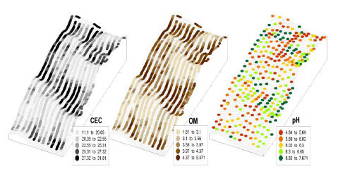
Topography and landscape position frequently exert a significant influence on soil properties and consequently crop productivity, and can hence augment proximal soil sensing (Kitchen et al., 2003). With the advent of real-time-kinematic (RTK) and other high-grade GPS receivers, precise topographical measurements can be acquired simultaneously and co-located with proximal soil sensor readings. Figure 6 shows soil elevation, CEC, OM, and pH maps estimated by the multiple sensors for an IA field. The data have been collected at an adequate spatial scale to show pass-to-pass repeatability. The spatial structure of the soil properties is discernible even without sophisticated processes or interpolating.
|
|
Figure 6. Calibrated Veris MSP-3 sensor maps overlaid on elevation (courtesy Veris Technologies). |
Mapping of IA and MO Fields
In the spring of 2012, 23 fields in IA and MO totaling over 900 acres were mapped with the Veris EC and OM sensors. Several included pH sensing as well. Ninety-three soil cores samples from these fields were analyzed in the laboratory for OM, CEC and pH. The objective of this study was to compare soil sensor estimates of OM, CEC and pH with laboratory-determined values on a broad range of soils.
Sensor readings were well correlated with lab-analyzed measurements; errors were typically less than 0.3 for OM and 1.0 for CEC. Many fields had correlation coefficients over 0.90 R², with lower correlation scores on fields with low variability.
Soil Sensor vs. Soil Survey Maps
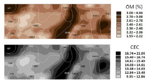
Data from an IA field shown in Figure 7 illustrates the improved definition provided by an on-the-go sensor such as the Veris MSP mapper compared to a soil survey. While the boundary for the Webster silty clay loam soil in the northwest corner (map unit 107) of the field corresponded closely to the spatial patterns for OM and CEC, this was not the case for the remainder of the field. For example, the survey lists the OM range for Clarion (138B) at 3% to 4% and CEC at 20 to 25 (meq 100g-1). Meanwhile, the calibrated sensor readings of OM within the Clarion soil ranged from less than 1.7% to greater than 3.5% and CEC values from less than 12 to greater than 20.
Soil survey inclusions and errors can present a serious problem if inputs such as seed and fertilizer are varied according to the expected productivity within a map unit. Even for a 2-acre inclusion, the minimum for a fine-scale soil survey, the included soil represents a ~325-foot × 325- foot area. A large 24-row planter would make at least 5 passes through that inclusion, potentially metering a severely suboptimal rate for the inclusion. Proximal soil sensors are typically operated on 50- to 60-foot transects, which more closely matches the capability of farm equipment to apply inputs site-specifically. With GPS and proximal soil sensors the location of changes in soil properties can easily be mapped within 3 to 6 feet. Sensor maps reflect the spatial pattern of soil as a continuum, identifying soil transitions precisely whether they occur gradually or suddenly, while soil survey lines can only depict soil differences as abrupt boundaries.
|
| Figure 7. Soil survey overlaid on OM and CEC Veris sensor maps (courtesy Veris Technologies). |
Hence, soil sensing tools can better characterize the within-field variability into MZ, and perhaps serve as better sources of information than soil surveys for deriving variable-rate prescriptions of crop inputs.


